Wireless technology can be challenging without the right combination of expertise and resources. The XBee is an arrangement of modular products that make deploying wireless technology easy and cost-effective. The module can communicate up to 100 feet indoors or 300 feet outdoors. It can be used as a serial replacement or you can put it into a command mode and configure it for a variety of broadcast and mesh networking options.
XBee and XBee-PRO RF modules are embedded solutions furnishing wireless end-point connectivity to systems. XBee modules are for extended range applications and they are intended for high-throughput applications requiring low latency and predictable communication timing. And they ideal for low power and low cost applications.
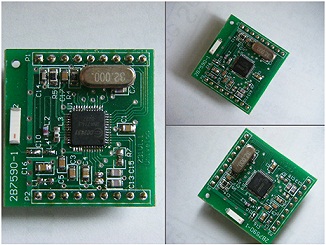
The very popular XBee module is 2.4GHz from Digi. These modules allow a very reliable and basic communication between microcontrollers, PCs, systems and support point to point and multi-point networks.
Features of XBee Module:
- Complete RF transceiver
- Onboard data encryption
- Automatic collision avoidance
- Low current consumption
- Wide operating voltage 1.8-3.6 Volts
- Operating frequency: 2.4-2.483 GHz
- Programmable output power and high sensitivity
- Data rate 1.2-500 kbps
The transceiver module furnishes a complete RF subsystem which can be utilized to transmit and receive data at up to 500Kbps from any standard CMOS/TTL source. Extensive hardware support is provided for packet handling, information buffering, burst transmissions and link quality implication. Automatic collision avoidance is additionally given with the clear channel evaluation features. The modules are ideal for battery powered applications.
How XBee Module Works:
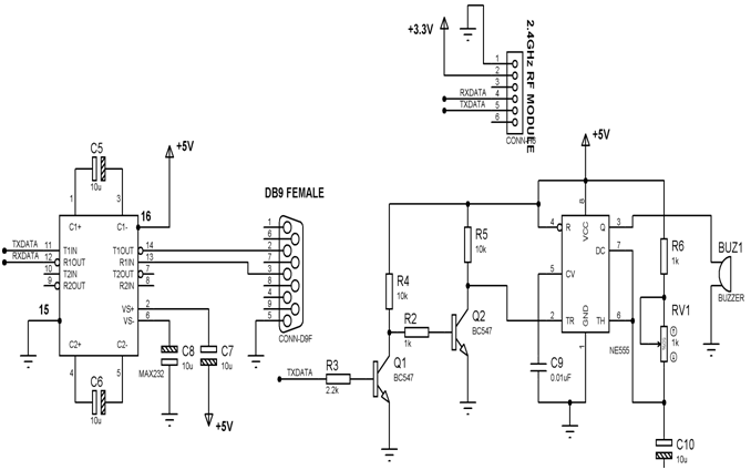
From the below circuit, we used two trans-receiver 2.4GHz XBee modules for two computers. The interfacing from the XBee modules is done through level shifter IC MAX232 as shown in figure. The modules are powered by on board regulated 3.3V power supply meeting the voltage requirement of the device by 3.3V regulator being fed after getting the 5V from regulator. In order to draw the attention of the recipient computer for the message received from the sender computer an audio beeping system is interfaced from the MAX232 Transmitter pin duly inverted two times by a pair of transistors Q1 and Q2 (BC547) to a 555 monostable multi-vibrator through its triggering pin2. Thus while any message is received at the transmitter pin of the MAX232 it also reaches the base of the Q1 resulting triggering of 555 monostable multi-vibrator timer to output from pin3 a buzzer sound. Hence it draws the attention of the recipient computer to respond to the message. R6, RV1, C10 form the time constant of the monostable timer 555 for the duration of the buzzer sound every time a keyboard key is pressed by the sender. It also has a provision to change the time constant by varying the RV1 to suit the recipient’s convenience.
0 comments:
Post a Comment